Still alive? 🪦
Yes, it’s true this project did get dropped for awhile, it’s been about 3 years since the last blog post.
Digital video Adapter (DiVA)
After implementing the SD controller I had kind of got to a limit of what I could get the hardware to do. Recall that this project was my first foray into FPGAs. However after seeing this project, GroupGets reached out interested in working on a digital video adapter PCB. The idea being a way to adapt the Boson to a digital video stream, like DVI or HDMI. FLIR already provide a “VPC” breakout, which stands for Video, Comms, and Power. However this cable provides composite video output, which isn’t great if you want to persevere the quality, or if you want to capture the full dynamic range.
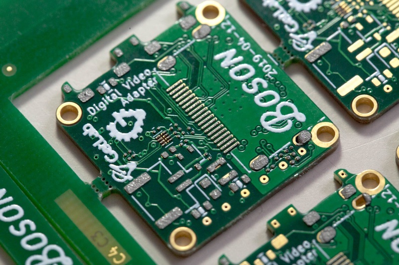
So that’s one of the boards I designed. Here are some assembly photos from the initial prototype to show that it was possible.
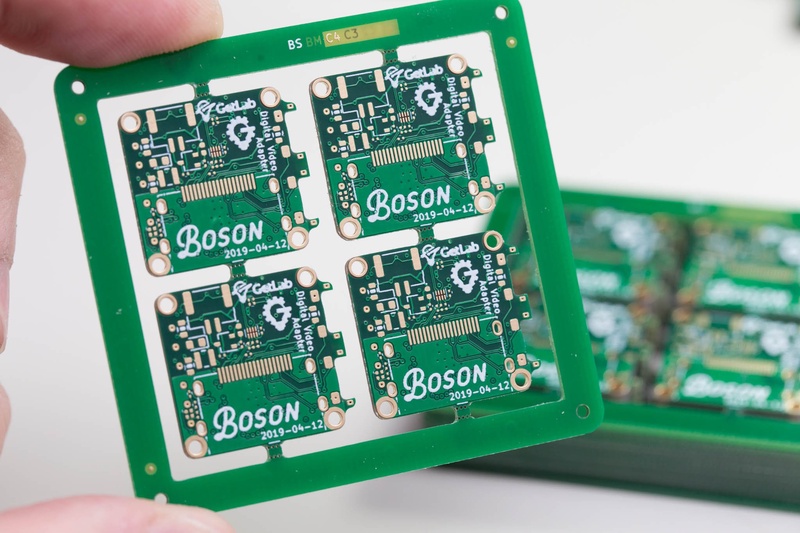
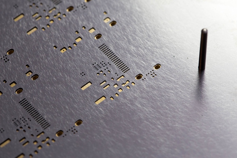
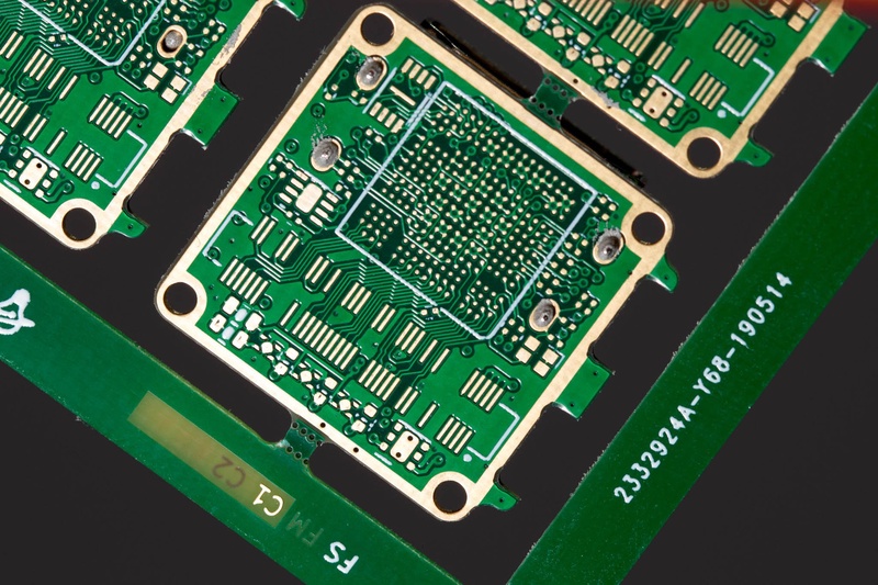
The PCBs were put into a small panel to make them a bit more manageable to assemble. The panel has some non-plated through-holes around it’s frame that align with features I put onto the stencil. This enabled the use of some 1.6mm steel pins to perfectly align the stencil to the PCB.
This actually works really well, the main issue I’ve seen is that you don’t want the pins to interfere with the squeegee action, here they are protruding a bit too high from the top of the stencil.
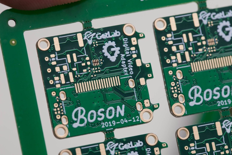
Solderpaste went down well, I’m using Loctite GC-10 here. The T4 variant.
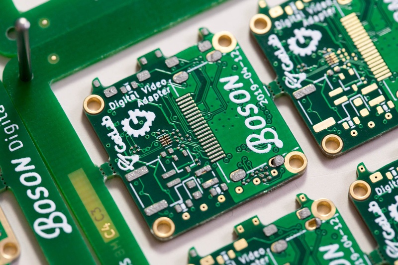
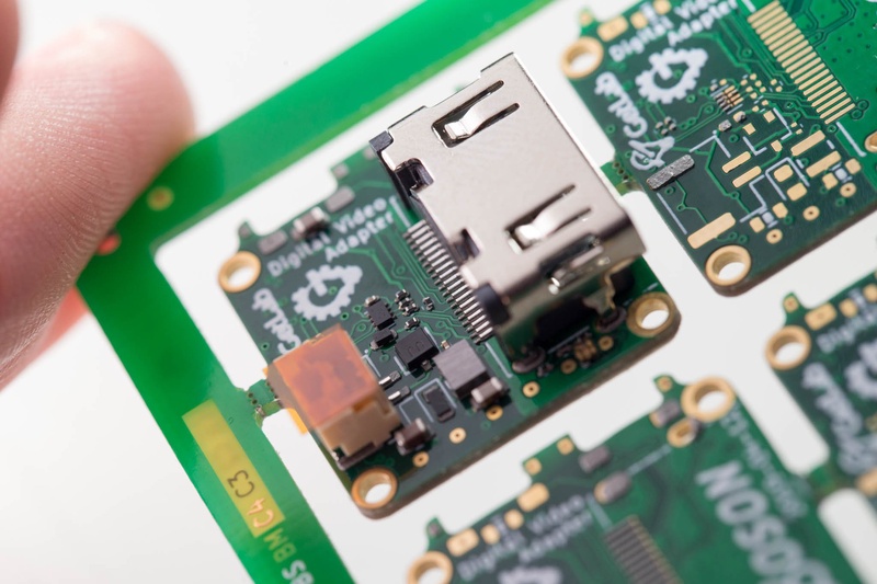
You can see in this image that I forgot that the HDMI connector has pins that protrude through the PCB. So if I had reflowed the connector I would not be able to sit a stencil flush with the second side of the PCB. Doh.
The fix was pretty simple, leave the connector off, reflow, then assemble the second side with an additional reflow cycle then hand solder on the HDMI connector.
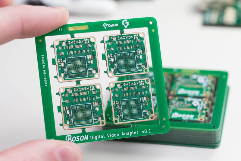
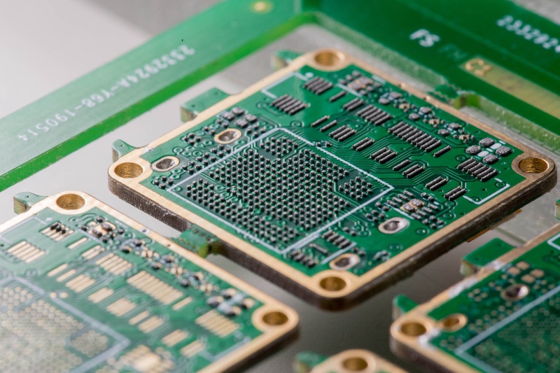
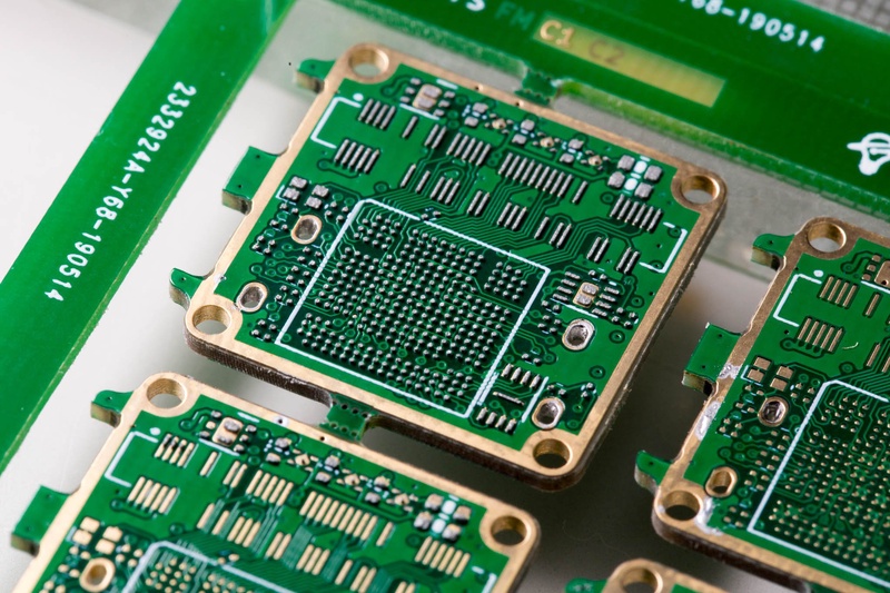
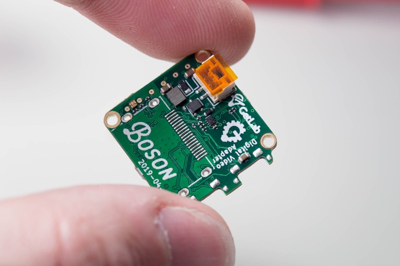
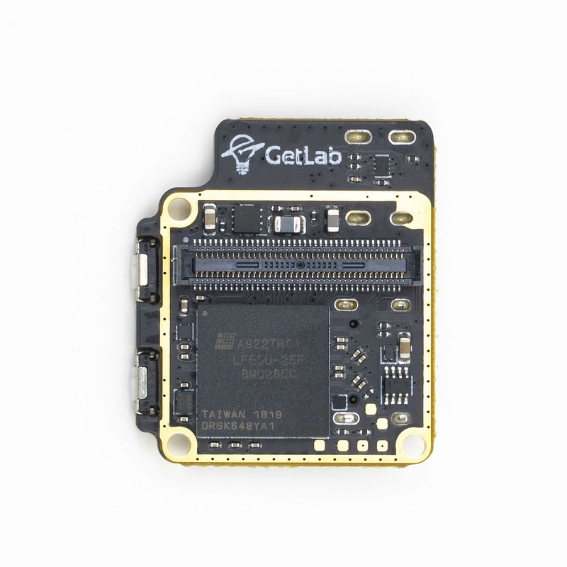
For extra units I simply soldered the FPGA side up first.
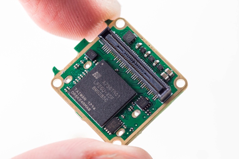
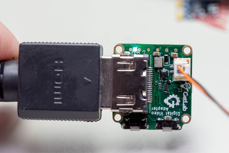
You can see the device very much resembles the boson-frame-grabber design.
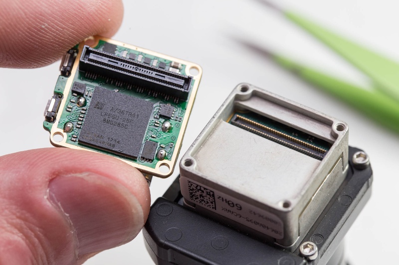
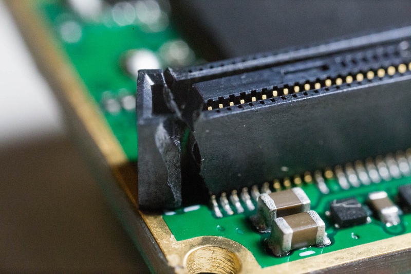
You do need to be careful with the 80-pin Hirose mezzanine connector. You really want to keep the two mated PCBs parallel when removing them. I unfortunately damaged a connector removing it.
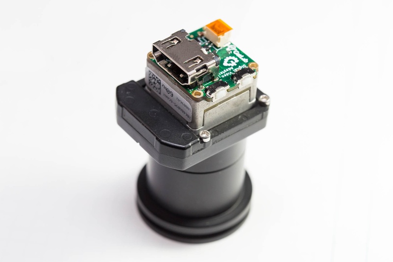
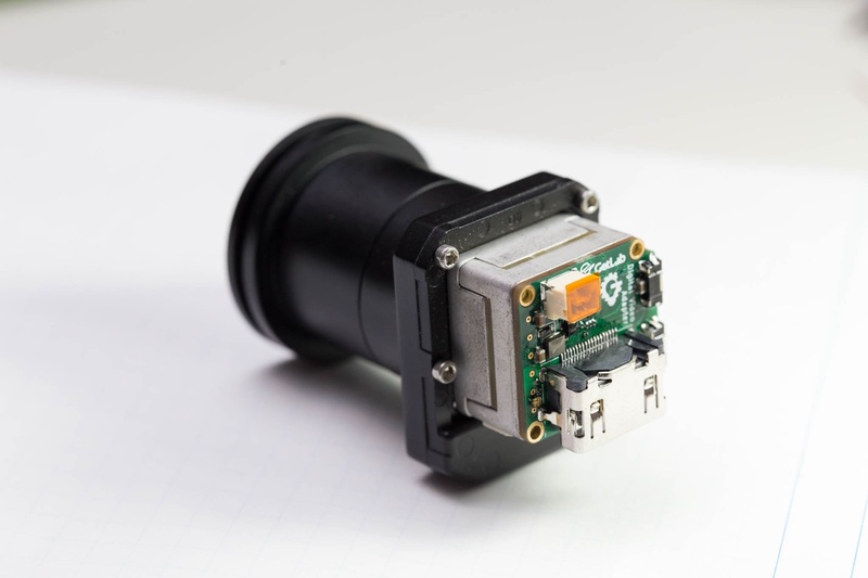
The full sized HDMI connector is a bit ridiculous given the size of the camera. So altough I typically don’t like micro HDMI connectors, this was actually quite a nice fit for this camera
This prototype did work. However because I didn’t include any RAM, the FPGA is only able to output a similar resolution, 640x512. In this case 640x480, with top/bottom rows of pixel removed.
This restriction is because we are essentially capturing a stream of pixels, and have to also output a stream of pixels to the display. In order for us to not run-out of pixels to send to the display We need to run the output clock rate a something very similar to the input.
Even with this hiccup, the prototype proved the design could work. So with the proof of concept done I started work on the design for a more production ready variant.
Inital production prototypes
Here is the initial production version, which turned out to have some layout bugs and issues.
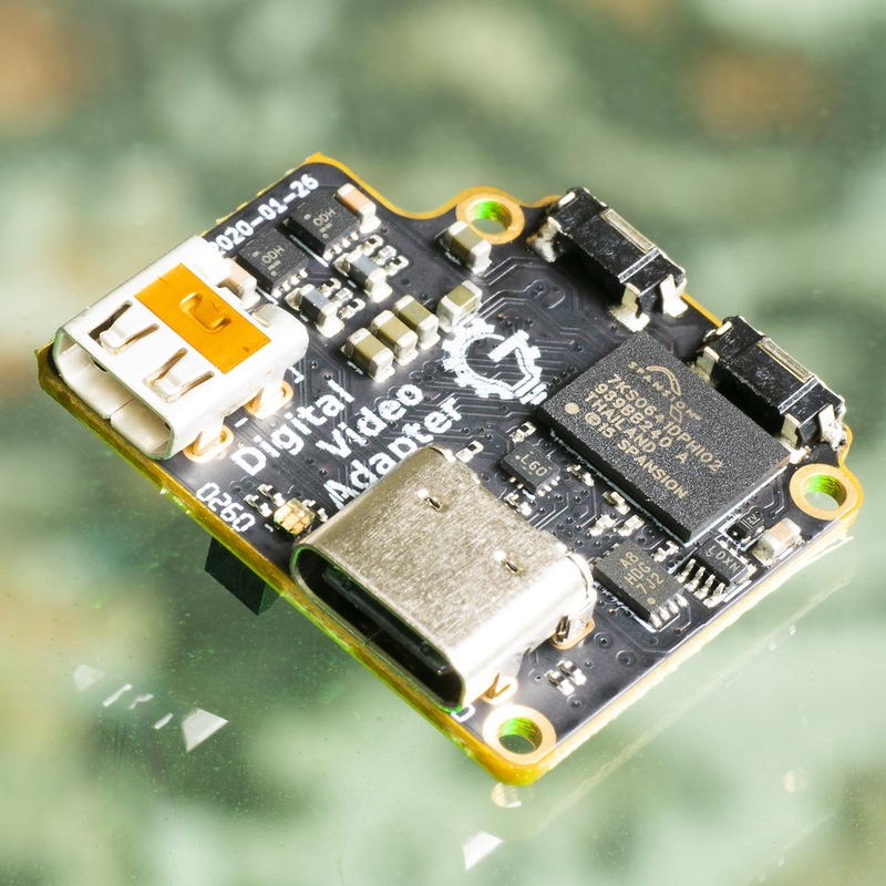
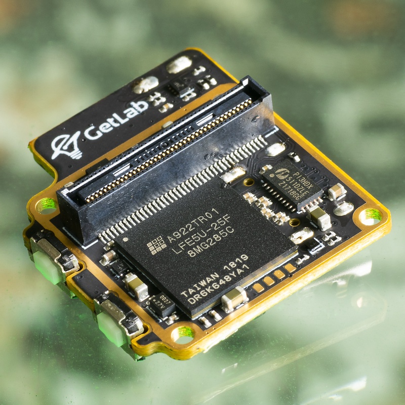
You can see I’ve added the hyperRAM back to the board, and also added USB C for power/and comms. The USB passes through a mux so you can use the Boson UVC device or talk to the FPGA at USB FS speeds. The USB is used to implement a bootloader that lets you update the device firmware/gateware.
Here is shot of the final production variant, that are available now on the group-gets store: https://store.groupgets.com/products/flir-boson-digital-video-adapter
DiVA gateware
The hardware for this camera is not open-source. But the gateware/firmware is! You can find that here: https://github.com/gregdavill/DiVA-firmware
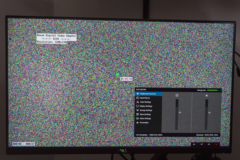
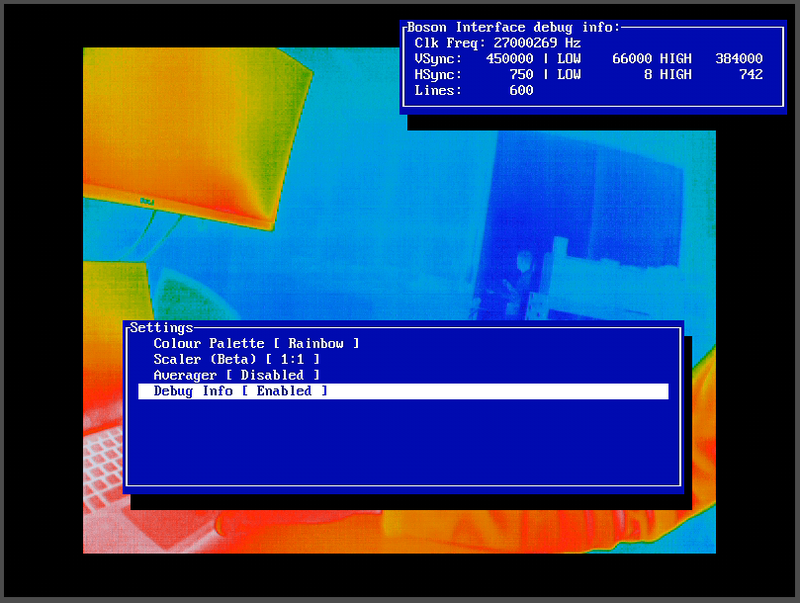
As an example of what the device does here is a capture of it’s output, with on-screen menus.
The current stable gateware is based on LiteX and Serv, LiteX is a collection of CPUs and peripherals along with plumbing to connect them all up. It’s written on top of migen, a method to describe and generate verilog from python. Serv is a serial RISCV implementation. It’s interesting because it’s quite small, therefore can run a quite a high frequency. However that higher frequency does need to overcome the fact that all instructions take at least 32 times longer to execute, because it’s a serial CPU, it’s internal data-path is only 1 bit wide, so to operate as a RISCV-RV32 it needs lots of extra cycles.
Compared to raw verilog, going around and finding cores, then connecting them together in a SoC design. I find using LiteX way more productive, but there is a bit of a learning curve.
The gateware that runs DiVA is essentially a SoC, HyperRAM controller, DMAs, and TMDS serializer. These components work together to capture a frame from the camera into memory, and then queue that frame for transmitting back out through the serializer.
v1.2 of the gateware also introduced a video scaler, which does appear to work, but might be distorting colours a bit, since it’s just combining R,G,B values linearly with coefficients from the scaler. I’ve been told that “proper” upscaling likely requires converting to a different colour space, combining colours, then converting back to RGB.
The scaler is a simple design I came up with after watching some lectures on multi-tap “polyphase” filters. The scaler only performs the up-scale operation. A stream of pixels comes through 4 “taps”. These taps cycle through coefficients that are loaded by the CPU. The coefficients have a flag to stall incoming pixels, but increment to the next step. This enables the upscaling operation. These coefficients are pre-calculated and match with a bilinear interpolation of the input to output ratio of scaling we want to achieve. I’ll probably try to make a more detailed blog post about that at some point.
The scaler can perform various stretch operations, since different coefficients are used for X/Y.
- Fill (crops top/bottom)
- Fit (borders on left/right)
- Center 1:1
- Full Screen (Changes aspect ratio)
There is also some buffering logic in there to enable coefficient banks to swap at the end of frame, to avoid graphical distortions while switching scaling options.
Updated DiVA gateware
There are a few open issues with the existing DiVA gateware, notably that it currently only supports 800x600 output resolution. And many HDMI transmitters expect at least 1280x720.
The hardware should technically support this, but someone needs to sit down and write the gateware to do it. I have started, but it’s far from complete yet.
I do also have plans to update the video pipeline to support more “modern” looking GUIs. But that work isn’t completed yet. For the time being, here is a demo image, showing various GUI elements ontop of a noise source. Also note that it’s output at 1280x720 resolution.